
When it comes to advancements in healthcare, we have a lot to be thankful for. Because of anesthesia, patients no longer need to “bite the bullet” during surgery. Thanks to antibiotics, doctors don’t use bloodletting to cure an infection. Moving into more modern times, radio-frequency identification (RFID) systems offer a wide variety of innovative healthcare applications. However, like any new medical technology, biomedical RFID devices must be rigorously evaluated for performance and compatibility with other medical systems.
Enhancing Patient Care with RFID Systems
RFID technology is common in many industries. In healthcare, though, there is a major design challenge: size. RFID tags on the smaller end are about the size of a grain of rice, but for cellular-level uses (such as research and diagnostics), the designs need to be even smaller.
A group of Stanford researchers developed an RFID tag that is small enough to be implanted in a cell, such as a skin or cancer cell. The size of the tag is about one-fifth the thickness of a human hair. It works in conjunction with a specialized RFID reader that interprets the data and monitors the cell’s activity in real time. These tiny RFID tags also have the potential to be linked to sensors for advanced biomedical treatment, such as antibody detection and the destruction of cancer cells.
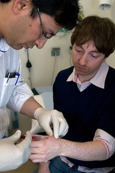
A surgeon implants an RFID microchip into the hand of a doctor. Soon, these tags could be implanted into single cells. Image by Paul Hughes — Own work. Licensed under CC BY-SA 4.0, via Wikimedia Commons.
No matter how good a doctor’s bedside manner is, patients don’t particularly enjoy being poked and prodded in order to get their vital signs taken. At Cornell University, researchers design ultrahigh frequency (UHF) RFID tags that can be used to monitor vital signs, such as heart rate, breathing, and blood pressure, without even touching a patient. The tags, which can be put into hospital wristbands or even sewn into clothes, communicate with an RFID reader that monitors multiple people in range simultaneously. The system relies on back-end software to manage, interpret, and monitor the data. This way, doctors get a clearer picture of each patient’s vital system performance, medical professionals save time and energy taking vitals, and patients are happier.
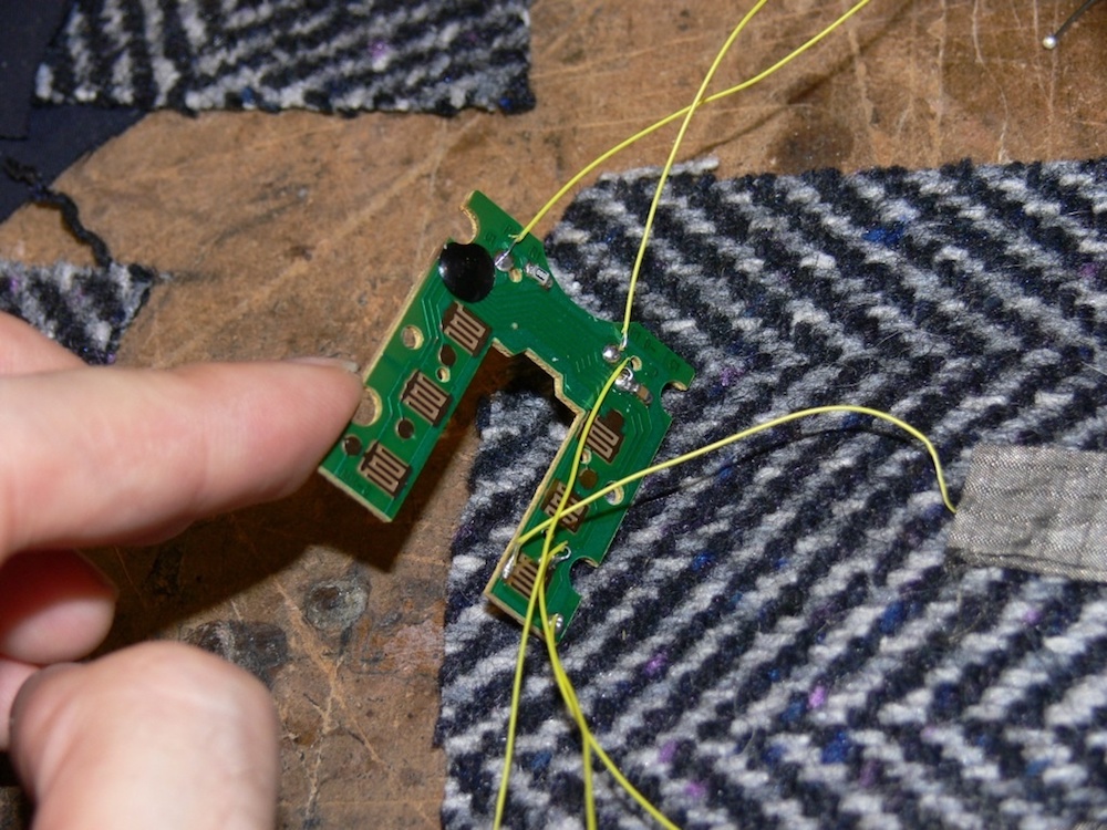
“Smart fabrics” are one potential application area of RFID systems. Image by Joshua Dickens. Licensed under CC BY-SA 2.0, via Wikimedia Commons.
Sleep disorders and sleep apnea are areas of biomedicine that often go untreated. Although they can lead to myriad health and safety issues, overnight sleep tests are costly and disruptive to a patient’s schedule, and at-home tests can be difficult to use. (I’ve personally undergone an at-home sleep test and it was extremely uncomfortable and awkward to strap the system around my torso, tape the breathing tubes to my face, and keep the monitor on my finger from falling off.)
To offer help in this area, researchers from RADIO6ENSE, the University of Palermo, and the University of Roma developed a passive RFID system for tracking sleep patterns remotely and in real time. The user-friendly passive RFID system involves RFID tags sewn into pajamas that don’t require any batteries and operate on a low power level, making them safe to use as wearables while they accurately collect sleep pattern data.
Considering EMI and EMC in Biomedical RFID Designs
Electromagnetic interference (EMI) and electromagnetic compatibility (EMC) are common phenomena in electromagnetics applications and can be analyzed with, for instance, EMC/EMI testing.
An anechoic chamber is one test facility used to test antennas for EMI/EMC.
EMI is of particular concern when it comes to RFID tags for biomedical applications, as an undesired mutual inductance can occur between devices and negatively affect performance, operation, and reliability. For instance, 2011 research from the National Center for Biotechnology Information says that RFID systems could be affected by contact with water, metal, or other devices (which is completely plausible in a medical scenario) — or RFID tags could negatively affect other medical devices. Additionally, a 2017 FDA report on RFID warns that EMI is a potential hazard when RFID systems interact with other medical devices.
When it comes to a patient’s well-being and safety, “potential hazard” is not a phrase healthcare professionals want to hear. That’s where simulation comes in…
Designing Optimized RFID Components in COMSOL Multiphysics®
Designers of RFID tags for biomedical applications need to account for the performance of tag and reader designs as well as how RFID affects other medical devices and systems. By characterizing a single device, such as an RFID tag, these designers have a good starting point for an EMI analysis. Electromagnetics simulation can be used to compute the mutual inductance of the RFID system design.
Improving Detection and Read Range in UHF Devices
Passive UHF RFID tags, like those mentioned at the beginning of this blog post, are preferred over their low-frequency and high-frequency counterparts because UHF tags can be detected at near and far distances from a reader, and can thus be used for a wide variety of applications. These tags also transfer data at fast rates and are more cost-effective to produce.
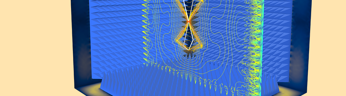
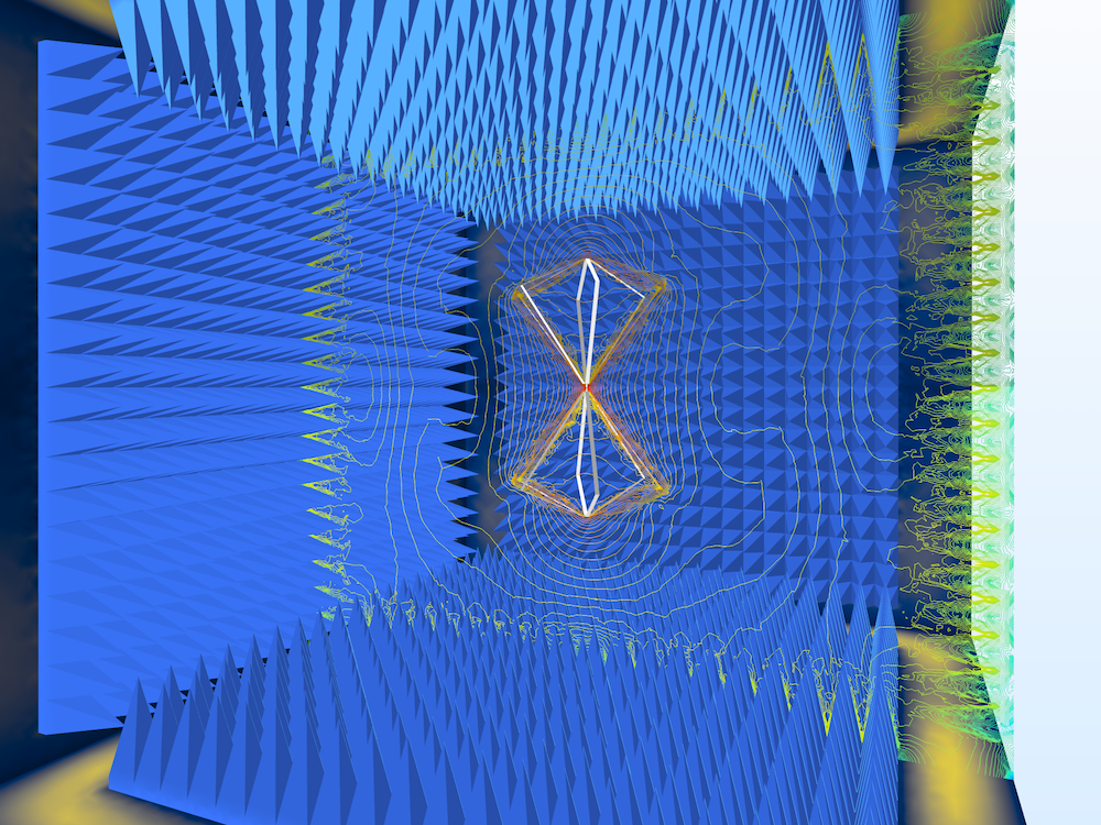
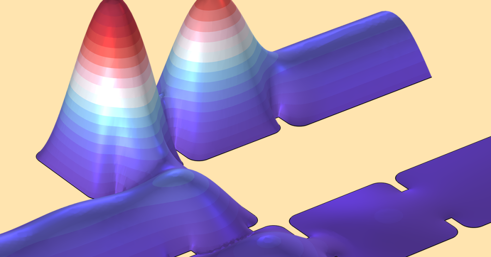
To evaluate the detection and read range of a UHF RFID tag, you can use the RF Module, an add-on to the COMSOL Multiphysics® software. RF simulation enables us to determine the default electric field norm, or E-field, for a tag design. This value can be used to predict the ideal placement of tags on a patient as well as the ideal placement of an RFID reader for tracking multiple patients at once.


Analyzing the E-field (left) and far-field radiation pattern (right) of a UHF RFID tag can improve the detection and range of the device.
Simulation analysis can also be used to find the far-field radiation pattern of a tag. For instance, in the model above, we can see that the radiation pattern is nearly the same in every direction on the plane of the tag. These results show that the RFID tag design is optimized for performance and has a long read range.
Ensuring the Safety of RFID Systems for Biomedical Use
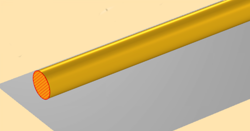
Consider a model of a basic RFID system, which consists of a reader-transponder with two main parts:
- Reader with large RF antenna
- Tag with a printed circuit board antenna


Geometries of a reader (left) and RFID tag (right).
The system works as such: The reader generates an electromagnetic (EM) field that energizes the chip inside the RFID tag. The EM field is altered by the tag’s circuit and the altered signal is recovered by the RFID reader’s antenna.
Using the AC/DC Module, an add-on product to COMSOL Multiphysics, and the Magnetic Fields interface, designers can simulate the inductive coupling between the reader and the tag. By finding the total magnetic flux intercepted by one antenna for current flowing in the system’s other antenna, you can compute the mutual inductance.
The simulation results below show the magnetic flux lines and the magnetic flux intensity between the RFID tag and reader. These results can be used to determine the mutual inductance of the system.
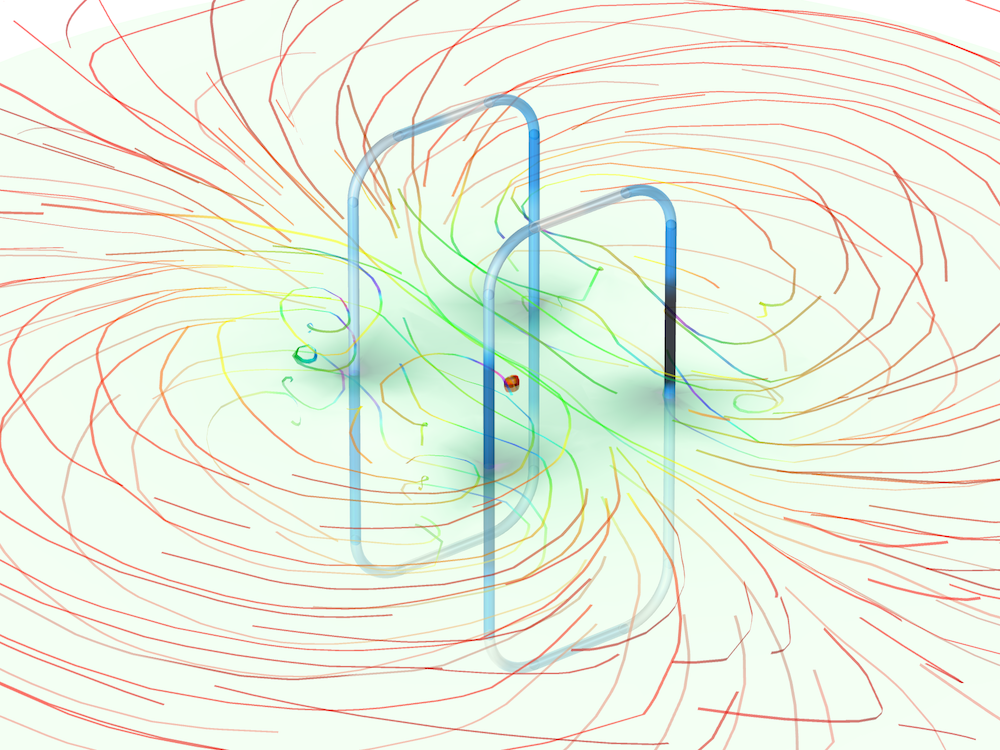
The magnetic flux density of an RFID system.
By finding the mutual inductance of an RFID system, you are able to predict its EMI with other medical devices. What’s more, you can design RFID tags that can be safely used to enhance healthcare in a variety of ways.
Next Steps
Find out what’s possible with the built-in functionality in the RF Module by clicking the button below.
Further Resources
- Try the models featured in this blog post:
- Learn more about applying simulation to RFID designs in this blog post: RFID Tag Read Range and Antenna Optimization

Comments (0)